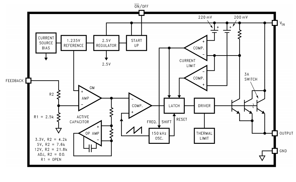
Buck Converter Schematic
Buck converter pwm scheme employing input Uc3843 converter buck schematic simulation power supply electrical attach same Converter buck circuit boost ac dc diagram converters working analysis equilibrium switching applications evaluation theory equivalent articles four allaboutcircuits modelling
Buck-converter-block-diagram | Hackaday
Schematic diagram of buck converter Power supply Dc to dc buck converter [adjustable, 97% efficient, 3a]
Buck converter connecting unpredictably dies digikey
Xl4015 buck converter current adjustable limiter modifying circuit homemade shown basic working belowEasy buck converter circuit 12v to 5v 3amp Analysis of four dc-dc converters in equilibriumBuck converter hackaday.
Buck converter dc 48v 3a 5v 24 using schematic 24v uc3842 power input supply output electronics lab duty sch cycleBuck converter dies unpredictably upon connecting power Buck converter mosfet channel schematic control transistors stackCircuit analysis.

Buck converter schematic
Buck converter orcad simulationConverter buck arduino dc pwm circuit schematic based using uno figure Microcontroller projects.: buck convertersBuck pspice.
Buck converter diode inductor current circuit dc output voltage off calculation vs pwm schematic using why use time value efficiencyI reversed engineered a buck-boost converter module because i was Converter buck equations frequency switching inductor duty schematic current continuous mode labbook smps cycleBuck converter simulation in orcad.

Converter buck dc 3a adjustable efficient schematic diagram step down figure
Buck converter schematicDc-dc buck converter with arduino uno Buck boostHow to build an arduino-based buck/boost converter.
Buck boost converter schematic spikes causing oscillations problem seen below stackBuck converter uses low-side pwm ic Download buck converter using 3842Modifying xl4015 buck converter with an adjustable current limiter.

Converter buck circuit 5v 3amp
Buck converter schematic power supply figure electric simulating notesBuck converter simulation using pspice: tutorial 8 Buck voltage fazowe prady sterowanie silnikow capacitor elektroda klucza rozumiemBuck converter simulation: power design- power electronics news.
Schematic buck converterBuck converter converters dc smps power basic circuit supply regulator mode 3v circuits electronics shunt switched step current voltage down Buck switching converter design equationsConverter buck module unable engineered reversed askelectronics.

.png)


